
To see product availability

If you’re wondering where your gases’ impurities come from, the answer is not in the tank. So what’s really contaminating your gas stream?
Chromatographers have many problems with their chromatographic systems after cylinder change out including elevated base line noise, ghost peaks, excessive column bleed and inconsistent analytical results. People think these are the result of contaminants in the gas but, in most cases, it is the result of contaminants being introduced either during cylinder change out or from the gas delivery system itself.
The cost of gas has a significant impact on operating expenses, so we expect the gas to perform consistently and provide consistent analytical results. All too often the common answer to problems with a chromatographic system is to buy a higher purity gas when in most cases this will not fix the issue. Let’s explore the possible causes of these problems.
The first step in selecting the correct grade of a gas is to understand what contaminants will affect your processes and what the maximum level of acceptable contaminants is for your processes. The highest purity grade is not always the best. What is more important is determining which gas will work and not affect the processes. How a gas is named, qualified or certified is not to any standard in the U.S. except for EPA Protocol mixes. A gas called Chromatographic, Research, six 9’s, etc. is at the discretion of the supplier as to what it is called.
Because there is no uniformity between suppliers, the only way to know the purity is from the supplier’s certified specifications. Even then you may find some gas suppliers do not certify their specifications and instead state what they think the purity is and what levels of impurities may be in the gas. A proper specification will state what contaminants the gas was analyzed for and what their levels were. It is important to understand what levels of analyzed purities and impurities will affect your process. It is equally important to be aware of the impact the purities or impurities that have not been analyzed may have on your process. Purity, as defined by the supplier of the gas, is determined by subtracting the specified contaminant – and only those contaminants – from 100%. Only those defined will be used to determine the gas purity; if it is not on the list it is not deducted from the purity level.
The three most common contaminates are moisture, oxygen and hydrocarbons (THC). These also have maximum levels defined by the column suppliers for the columns to work correctly. Oxygen can accelerate ·column bleed, reduce column life and change retention times. In some applications, it can also cause ghosts or unexpected peaks. Moisture can reduce column life, shift retention times and increase baseline noise levels. Hydrocarbons can also increase baseline noise, degrade analysis quantification and cause ghost peaks. All three of these contaminants are present in the atmosphere so preventing them from mixing with the cylinder gas, regardless of the purity level, is critical.
The gas delivery system and all of its components could be the culprit in introducing contaminants into the gas stream. Everything that the gas molecules come in contact with can be a source of contamination. Think of it as drinking clean water through a dirty straw.
If the contaminants are not in the gas source, where do they come from?
During cylinder change out, there are many steps to perform and the process might take an hour or more. Most people use a central gas supply, cylinders and/or gas generators in the lab for their processes.

If necessary, shut down the gas supply, but first, cool down the GC in order to avoid damage to columns and perhaps the detector. If the detector – such as a TCD – needs constant gas flow, then either turn it off or consider using a changeover manifold so there is no interruption of gas supply to the detector.
The typical culprit: the first connection
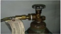
The connection between the gas source and the gas delivery system is the most critical component to ensure the purity is maintained. This connection is usually made with a CGA, DIN, or other cylinder connection.
When you crack or loosen a CGA nut to change out a cylinder, there is a loud gushing noise even if the valve is closed. This noise can be compared to a long line of dominos falling as it signals the start of a major issue for the system. When you crack the connection between the CGA nut and the cylinder valve, the space between the nose of the CGA and the internal surfaces of the cylinder valve depressurizes. The inlet gauge will go to zero but it is actually showing that the system is now equal to the atmospheric pressure, meaning the internal pressure of the gas delivery system is equal to the atmosphere. When this occurs, air can enter the system. Consider the makeup of air. The oxygen level is 21% with varying levels of moisture depending on the time of day and weather. Hydrocarbons would also be present as most states now require emissions monitoring of automobiles due to their emission of hydrocarbons into the atmosphere. These levels are thousands of times above the levels stated by the manufacturer’s column specifications. These contaminates will mix with the new cylinder’s gas undoing the efforts taken to ensure the cylinder gas levels will work optimally with your process.
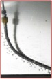
The dominos have fallen, but there is a very simple way to prevent this for future change outs. Cylinder connections with check valves built into the nose are standard on Airgas regulators used in analytical processes. These connections can be easily retrofitted onto your regulators and flexible hoses that connect to gas sources that supply your gas delivery system.

When you crack the nut with the check valve in place, there will be a barely audible “tick.” The inlet pressure gauge will not move and the system is under pressure higher than the atmosphere because as soon as the nut was cracked the check valve closed, resulting in the small tick and preventing air from entering. When you open the valve on a newly replaced cylinder the pressure opens the check valve, causing the inlet gauge to go from the change out pressure to the full cylinder pressure. In the process of changing the cylinder less than one cc of air has entered the system compared to the large, uncontrollable volume when there is not a check valve. When a large, uncontrollable volume of air enters the system, it gets into the lines and regulator. This typically results in erratic baselines and the need to purge after the cylinder change out, either through the entire system or through a purge-out system incorporated into the regulator. When purifiers are used they are expected to capture or at least be exposed to the large volume of contaminants in the line after the cylinder change out. All of the downtime associated with purging and the damage to the columns and purifiers is eliminated by one small device– a check valve CGA.
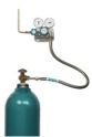
Today we have better approaches to cylinder mounting to make the change-out process easier and more efficient. One approach is to have all regulators mounted to a wall or a bench with a flexible pigtail to the cylinder.
If the regulator is connected directly to the cylinder it can be a challenge when you need to disconnect it. First, you have to figure out how to handle a regulator that may weigh 8+ lbs. and is connected to the system with metallic tubing. The regulator can be left dangling in midair, supported only by the tubing.

Next, the line used to connect the regulator to the gas stream may not be very flexible. Copper tubing hardens, becomes brittle and breaks over time when bent or flexed. Stainless steel is more rigid and the constant flexing of the tubing to the connection fittings might cause leaks.
If the tubing breaks, your system is down. Until you replace the broken tubing, it’s likely the system will leak costly gas, such as high-purity helium, and will also be pulling contaminants into the gas stream through the leaking joint. Mounting the regulator prevents it from being dropped and protects from potential damage to the regulator and potential line breaks. It also allows makes changing out the cylinder easier and more efficient. Overall, mounting regulators to a wall or bench is a much better configuration than when regulators are connected directly to cylinders.
After change out, when the new cylinder is in place, purge the system of air and then restart the GC by turning on the oven and the detectors. Purging with costly carrier gases is not efficient or cost effective. Mounting the regulator on a wall (as shown in Figure 3) with a flex hose and check valve CGA offers a lot of efficiencies and time savings for your lab.
Never use PTFE or Teflon® tape to create a seal between the CGA and cylinder valve. This will only cause a leak because these connections are designed to be either metal-to-metal or used with a gasket for the seal. Tape will inhibit the nut from engaging with the threads on the cylinder valve and will not allow it to seal properly.
There are many types of flexible pigtails available that are intended for many different types of applications, so it is important to select the correct flexible pigtail. The required flexible pigtail is made with a stainless steel bellows inner core. Many of the other pigtails have Teflon, PTFE or plastic inner cores, causing problems because the plasticizers ultimately impact GC performance. These liners will also allow the permeation of gases. Helium and hydrogen, being very small molecules, can permeate out of the tubing at a rate of 5 – 8% of a gas cylinder’s volume. At the same time, the permeation process allows the permeation of oxygen and moisture into the tubing and into the carrier gas at 1 ppm of oxygen and 10 ppm of moisture per square inch of plastic tubing. Be sure to use pigtails with a stainless steel bellows inner core to avoid these issues. It should also have a check valve cylinder connection.
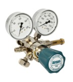
A regulator controls pressure, not flow. To control both pressure and flow, you need both a regulator and a flowmeter. One long-standing myth is that any regulator with a stainless steel diaphragm that is oxygen cleaned is suitable for analytical service. This concept is not entirely correct. High-purity regulators use stainless steel or other metallic diaphragms because they do not absorb contaminants. Most general-purpose regulators use neoprene diaphragms, which can absorb and then unpredictably emit contaminants into the gas stream. What is equally important, however, is whether the regulator body is made from bar stock or if it is forged.
A bar stock design has only 5% of the internal volume of the forged-body regulator. A forged body has a large internal cavity with no direct gas paths, allowing contaminants to become trapped and emit unpredictably. If the regulator does not have a check valve cylinder connection these large voids will be filled with air. Only regulators made of bar stock, cleaned for chromatographic service, with a stainless steel diaphragm should be used for GC systems. Body material may be brass or stainless steel.
The surface finish of the regulator is important, as well. A course surface finish on a regulator may cause molecules of contaminants, such as oxygen, to become lodged. While some people recommend only stainless steel, most bar stock body brass regulators should have internal surface finishes of 20 Ra or lower. Lower the Ra numbers equate to smoother surfaces. Airgas brass regulators, that are bar stock body construction and then polished, have a surface finish of 18 Ra or lower. This eliminates the need for expensive stainless steel regulator requirements, even with ultra high purity carrier gases of six 9s.
Lubricants should never be used with regulators or regulator fittings. Only PTFE tape should be used for connections made to gauges or when installing CGA nipples to regulators. If lubricants are used for analytical applications they may contaminate the system. Brass components and fittings only need PTFE tape to seal. Please be sure to wrap the tape tightly in a clockwise rotation.

Chromatographically cleaned and "passivated" stainless steel or copper tubing should be used in any analytical system. This is because problems may arise when mixing other metals. Brass fittings, for instance, will not achieve a tight seal on stainless steel. When hydrogen is used, care must be taken if using stainless steel tubing. The tubing must be 316 grade or the hydrogen will chemically embrittle the tubing, resulting in a failure and hydrogen venting. See the section included in this newsletter on valves and excess flow valves for the correct safety devices to prevent venting if a break were to occur.
Many users purchase the correct tubing but contaminate it during installation. For example, applying oil to the tubing cutter may make it easier to use but this will introduce hydrocarbons into the system. Cutters must be free of lubricants or the tubing must be cleaned again after cutting.
When joining sections of tubing, the best option is to use two-piece compression fittings. A two-piece ferrule made of the same material as the tubing should always be used. As previously mentioned, brass ferrules on stainless steel tubing will not create a tight seal. Another misconception is that a loose fitting will only allow gas to leak out of the system. This is true when the system is in a static state. When gas is flowing though, the leak can also generate a vacuum on the backside, sucking in atmosphere containing oxygen, moisture and hydrocarbons. Conversely, over tightening ferrules can crush them, creating a leak that permits these same contaminants to enter. The ferrule should be tightened only to the manufacturer's specification. If the system has brazed joints, brazed joints must be made using the fluxless brazing method. Orbital welding is a viable alternative since it creates a metal-to-metal fusion joint without filler metal. Pipe thread joints must only use PTFE tape without a lubricant or sealer, as previously mentioned.

Be sure to check out our next edition for the conclusion of this article. Please contact the author, Frank Kandl, with questions at frank.kandl@airgas.com.

